Previous Contents Next

Chapter 2   The Scheduling Algorithm

2.1   The DLX Architecture

The underlying CPU is an implementation of the DLX architecture [HP96]. That is a load/store architecture with support for integer and floating point instructions. It has three register files:

The DLX instruction set (appendix C) is a RISC instruction set and is similar to SUN's MIPS instruction set.

2.2   The Tomasulo Scheduling Algorithm

The following sections give a short summary of the Tomasulo scheduling algorithm. The algorithm was specified in 1967 by Robert M. Tomasulo for an IBM 360/91 [Tom67]. A more comprehensive description is also available in [Mül97a].

In its original form, the Tomasulo scheduling algorithm is limited to two-address-instructions (one source, one destination, e.g., R1+=R2) and multiple sequential function units for each kind of operation. However, it is easy to extend the algorithm to handle today's common instructions with three addresses (two source registers, one destination, e.g., R1:=R2+R3). The algorithm is widely used, e.g., by IBM PowerPC, Intel Pentium-Pro or AMD K5 [Mot97, CS95].

2.2.1   Pipelining vs. Out-of-Order Execution

Pipelining

There are many ways of implementing the execution of an instruction. In general, the execution of an instruction can be split into the following phases:


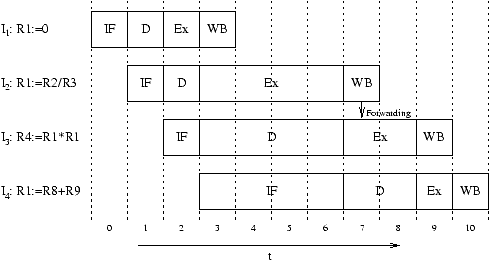
Pipelined CPUs overlap the processing of different phases of different instructions. The first approach is to process the single phases of the instructions strictly in program order. Figure 2.1 illustrates this. Pipelining implies in-order execution, i.e., the execution of the subsequent instructions is also done strictly in program order.


Figure 2.1: Pipelining example


However, in-order execution does not fully utilize all functional parts of a CPU. The rule of in-order execution prohibits that subsequent instructions overtake previous instructions. In figure 2.1, instruction I2 blocks the execute stage for four cycles, since the division function unit has a long latency. Instruction I3 has to be stalled upon the begin of its execution, since the execution stage is blocked by I2 and since it requires the result of I2 (data dependence).
Out-of-Order Execution

Data dependencies and different latencies of the function units can cause additional delays which reduce performance. In order to eliminate these delays, the rule of in-order execution of all instruction phases must be dropped. The result is an out-of-order execution algorithm. An out-of-order execution algorithm tries to increase performance by distributing the instructions among the available hardware components regardless their original order. There are two main requirements for such an algorithm:

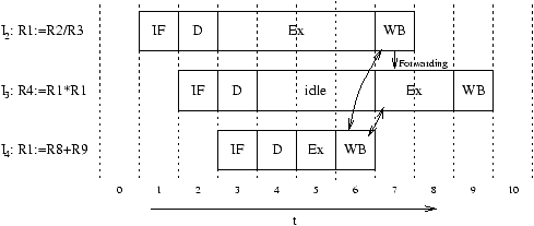
Figure 2.2 depicts the execution of I2 to I4 on an out-of-order CPU. Instruction I4 is now able to enter the execution stage even before I3 does, since I4 does not depend on any result of the preceding instructions. It even terminates before I2, which causes a write after write (WAW) data hazard in R1 [HP96].

Furthermore, I3 tries to read R1 before I2 writes it. Thus, there is also a read after write (RAW) data hazard. Since I4 writes R1 before I3 reads it, there is also a write after read (WAR) hazard.

There are several ways to resolve these hazards. In order to resolve RAW hazards, result forwarding is usually used. In the given example, the result of the division is forwarded to instruction I3. The scheduling algorithm is supposed to stall the execution of an instruction until all operands are available.

One way to resolve WAW and WAR hazards is to skip the writeback of a result into a register if a subsequent instruction, which writes into the same register, already terminated. In the given example, the writeback of the result of instruction I2 would have to be skipped. The result is forwarded to instruction I3 instead. This is implemented by the Tomasulo scheduling algorithm in its original form.

Another way is to delay the result writeback until all previous instructions wrote their result into the register file, i.e., the writeback is performed in-order. This is implemented by the Tomasulo scheduling algorithm with reorder buffer used in this thesis.


Figure 2.2: Out-of-order execution example. Instructions I2 and I4 cause a WAW hazard, instructions I2 and I3 cause a RAW hazard, and instructions I3 and I4 cause a WAR hazard.


2.2.2   Basics of the Tomasulo Scheduling Algorithm

The Tomasulo scheduling algorithm has several essential features:

Please note that the original Tomasulo algorithm uses out-of-order termination and thus does not support precise interrupts. In order to support precise interrupts, a reorder buffer (ROB) [SP88] is added to the machine described in this thesis. The reorder buffer implements in-order termination. This results in small modifications of the original scheduling algorithm. Thus, the following sections describe a modified scheduling algorithm presented in [Ger98] rather than the original Tomasulo scheduling algorithm. The complete protocol is presented in section 2.4, and its hardware implementation is presented in chapter 3.

2.2.3   Key Data Structures and Transfer Paths


Basic structure of an in-order design   After adding Tomasulo scheduling

Figure 2.3: The basic data structures and data paths before and after adding Tomasulo scheduling


Figure 2.3 gives an overview of the basic data paths of an in-order design and of the same design after adding Tomasulo scheduling with reorder buffer. The Tomasulo scheduling algorithm requires the following data structures and transfer paths:

Each register (named Ri.data) is extended by a tag and a valid flag. This extension is called producer table. These additional data fields have the following purposes:

Each function unit is extended by an instruction buffer to store instructions and operands until all operands and the function unit itself are available. These buffer entries are called reservation stations.


Figure 2.4: Reservation station data items


The reservation stations provide the operands for the function units. They are basically a queue for the issued instructions. Each reservation station RSi holds exactly one instruction and its operands and has the following components (figure 2.4):

The instructions are written into an appropriate reservation station during instruction issue. As soon as all operands of a given instruction in the queue (i.e., in a reservation station) are available, the instruction is ready to be dispatched into the actual function unit.

The result bus of the in-order design is replaced by the common data bus (CDB). During instruction dispatch, the instruction is passed to the function unit. On leaving the function unit, the CDB is requested for writing the result on the CDB. Functional units writing on the CDB are called producers. Units reading the CDB are called consumers. The reservation stations are the usual consumers. They watch the CDB for the operands they are missing (bus snooping). However, before a producer can write on the CDB, it has to request the CDB, since multiple producers might try to write on the CDB in the same cycle. These requests are handled by the CDB control, which acknowledges at most one request in the next cycle (in the original Tomasulo design, even two cycles of lead time are required).

2.3   The Reorder Buffer

In order to realize precise interrupts, the design in this thesis contains a reorder buffer (ROB). Precise interrupts are essential for today's microprocessors. An interrupt between instruction Ii-1 and Ii is precise iff instructions I1,...,Ii-1 are completed before starting the ISR and later instructions (Ii,...) did not change the state of the machine [SP88, Mül97b].

On completion, the reorder buffer [SP88] gathers the results produced by the function units and sorts them by issue order, i.e., by program order. The results are written afterwards into the register file in issue order. However, before writing the result of instruction Ii, it is checked whether this instruction causes an interrupt or not. Thus, in case of an interrupt, the register file contains exactly all modifications made by instructions I0 to Ii-1.

The reorder buffer is realized as circular FIFO queue with a head and a tail pointer. New instructions are put into the ROB entry pointed to by the tail pointer. This ROB address is also used as a tag to the result. This is in contrast to the original Tomasulo design, which uses tags associated with the reservation stations. Table 2.1 lists the main components of a reorder buffer entry. The ROB needs further extensions in order to support interrupts (chapter 3).


Name Width Purpose
valid 1 valid =1 Û data field contains a valid value
data 64 result data
dest 4 address of the destination register

Table 2.1: Main components of a reorder buffer entry


When an instruction completes, both the result and the exception flags are written into the reorder buffer entry pointed to by this reorder buffer tag. In each cycle, the entry at the head of the reorder buffer is tested. If it is valid (i.e., the instruction has completed), a check for exceptions is performed and the data is written into the register file. Depending on the type of the interrupt (abort/repeat/continue), the result of Ii is written into the register file before executing the interrupt service routine.

2.4   The Overall Scheduling Protocol

The following section presents the overall scheduling protocol, which is implemented in this thesis [Mül97a, Ger98, Del98]. The execution of an instruction Ii is split into six phases: fetch, issue, dispatch, execution, completion and writeback.


2.4.1   Issue

Let Ii be the instruction to be issued. For issue, it is essential that an appropriate reservation station and a ROB entry are available -0.5ex (figure 2.5). If so, the instruction is issued into this reservation station entry -0.5ex . For each operand of the instruction three sources have to be checked -0.5ex : The operand might be in the register file -0.5ex , on the CDB -0.5ex , or in the reorder buffer -0.5ex . If not, it is the destination of a preceding, incomplete instruction -0.5ex , and instead of the operand, the tag of this instruction is stored in the reservation station.

Simultaneously, the ROB entry is allocated and initialized for the instruction -0.5ex . If the instruction has a destination register, the address of this register is stored in the ROB entry and the pointer to the ROB entry is stored as tag in the producer table. After issue, the tail pointer is incremented -0.5ex .


Figure 2.5: Issue protocol. The register address of operand x is denoted by x.A.


2.4.2   Dispatch

During instruction dispatch (figure 2.6), a valid instruction moves from a reservation station entry into the actual function unit. An instruction is valid iff all its operands are valid -0.5ex . Furthermore, the function unit must not be stalled, i.e., it must be ready to accept a new instruction. If more than one instruction for a certain function unit is valid, the scheduler has to choose one for dispatch. The correctness proof in chapter 6 relies on choosing the oldest among the valid instructions. This issue is discussed in chapter 3. If all these conditions hold, the instruction is passed to the function unit -0.5ex and the reservation station is freed -0.5ex .

In real hardware, RS.opx can also be forwarded via CDB from a producer. In contrast to the forwarding during issue, this forwarding is just an optimization and not necessary for correctness. Thus, this protocol element is omitted here.


Figure 2.6: Dispatch protocol


2.4.3   Completion

Before completion (figure 2.7), the reservation station requests the CDB. As soon as the reservation station gets an acknowledge -0.5ex , the result and the ROB tag are put on the CDB -0.5ex . The according reorder buffer entry is filled with the result and the valid bit is set -0.5ex .


Figure 2.7: Completion protocol


2.4.4   Snooping on the CDB

On completion, the result of an operation is put on the CDB. Instructions in the reservation stations, which depend on this result, read the operand data from the CDB (figure 2.8). The reservation stations identify the results by the ROB tag.


Figure 2.8: CDB snooping protocol


2.4.5   Retirement / Writeback and Interrupts

During retirement (figure 2.9), a result of an instruction in the ROB is written into the register file -0.5ex , if no interrupt of type abort or repeat is pending -0.5ex .

At the same time, the result flags are checked -0.5ex . Almost all result flags are masked with the SR registers prior this check. If an error occurred while processing the instruction, the interrupt service routine is started. Section 3 contains more details of the interrupt mechanism.


Figure 2.9: Retirement / writeback protocol


2.5   Overall Scheduling Example

Figure 2.10 contains an example of Tomasulo scheduling with reorder buffer, considering the following piece of code:

    I1: R3:=M[R10]
    I2: R1:=R2+R3
For this example, M[R10] contains the value 11 and R2 contains 9. In cycle t=0, the first instruction is already in the execution phase. It is executed by the memory unit and stored in reorder buffer entry 0. Furthermore, in cycle t=0 the second instruction is fetched.

In cycle t=1, this instruction is decoded and issued into a ALU reservation station. The ALU reservation is assumed to have only one reservation station. The reorder buffer entry 1 is also filled with this instruction.

In cycle t=2, the load instruction is one cycle ahead of completion. Thus, the memory reservation station requests the CDB for the next cycle.

In cycle t=3, this request is acknowledged by the CDB control. The result of the load operation (11) is put on the CDB. This makes the second operand of the ALU reservation station valid. Since both operands are now valid, the instruction is dispatched into the ALU in the same cycle. Furthermore, the ALU requests the CDB for the next cycle. In the same cycle, the result of the load instruction on the CDB is written into the reorder buffer entry 0, which becomes valid.

In cycle t=4, the result of the load instruction is written from the reorder buffer entry 0 into the register file. R3 becomes valid by this. In the same cycle, the CDB control acknowledges the CDB request by the ALU. The result of the addition is put on the CDB and reorder buffer entry 1 becomes valid.

In cycle t=5, this result is finally written into the register file.


  ALU reservation station for I2 register file
t global operand 1 operand 2 R1 R2 R3
  op tag full tag valid data tag valid data tag valid data tag valid data tag valid data
0 - - 0 - - - - - - - 1 0 - 1 9 ROB-0 0 -
1 + ROB-1 1 - 1 9 ROB-0 0 - ROB-1 0 - - 1 9 ROB-0 0 -
2 + ROB-1 1 - 1 9 ROB-0 0 - ROB-1 0 - - 1 9 ROB-0 0 -
3 + ROB-1 1 - 1 9 ROB-0 1 11 ROB-1 0 - - 1 9 ROB-0 0 -
4 - - 0 - - - - - - ROB-1 0 - - 1 9 ROB-0 0 -
5 - - 0 - - - - - - ROB-1 0 - - 1 9 - 1 11
6 - - 0 - - - - - - - 1 20 - 1 9 - 1 11


  reorder buffer common
t global entry 0 entry 1 data bus
  ROB.head ROB.tail valid data dest valid data dest req ack tag valid data
0 ROB-0 ROB-1 0 - gpr R3 - - - - - - - 0 -
1 ROB-0 ROB-2 0 - gpr R3 0 - gpr R1 - - - 0 -
2 ROB-0 ROB-2 0 - gpr R3 0 - gpr R1 Mem - - 0 -
3 ROB-0 ROB-2 0 - gpr R3 0 - gpr R1 ALU Mem ROB-0 1 11
4 ROB-0 ROB-2 1 11 gpr R3 0 - gpr R1 - ALU ROB-1 1 20
5 ROB-1 ROB-2 - - - - 1 20 gpr R1 - - - 0 -
6 ROB-2 ROB-2 - - - - - - - - - - - 0 -


Figure 2.10: Scheduling example


Previous Contents Next